To record your own sounds, you have to understand what's happening between the air in front of a microphone and the file on your computer. This reading takes the path one stage at a time, through the four pieces of equipment in a simple recording chain: a dynamic microphone, an XLR cable, an audio interface, and a computer.
1 · Signal flow
Every recording setup has a signal flow. That's a fancy phrase for a simple idea: sound starts somewhere (a voice, a guitar, a slammed door, a crumbling sheet of paper) and ends up stored somewhere (a file on a hard drive). Between those two endpoints, the sound passes through equipment. Each piece of equipment has a job, and each piece is a choice. A different mic, a different cable, a different interface, and you get a different recording, even if the source is identical.
The signal flow you'll use most often, and the one a basic home or project setup is built around, is the basic recording chain. It has five stages: three devices, connected by two cables.
The basic recording chain. Three devices (mic, interface, computer), connected by two cables (XLR, USB).
Read the diagram left to right and you can see what's happening at each transition. A sound in the air vibrates the microphone, and the microphone produces a small electrical signal (this is what we'll call mic level, and it matters more than it sounds like it should). That signal travels down an XLR cable to an audio interface. The interface does two jobs: it amplifies the small mic-level signal up to something the computer can work with, and it converts that analog electrical signal into a stream of numbers (digital audio). Those numbers travel over a USB cable to the computer's audio input, where any recording program can read from them.
The five stages alternate: device, cable, device, cable, device. The devices do the work of converting and processing the signal; the cables carry the signal from one device to the next. Each cable type has a job that matches the kind of signal it carries: XLR for mic-level analog audio, USB for digital data.
Once you've read all the sections that follow, the diagram above should feel less like a sequence of mystery boxes and more like a list of decisions you understand. When you sit down to record, you'll be operating every stage of this chain.
This is one signal flow out of many. There are others worth knowing. A guitar plugged into the same interface uses a different cable carrying a different kind of signal. A condenser microphone needs power that this dynamic mic doesn't. A synthesizer puts out a signal at a different level entirely. The basic chain here is the most common one and the one most setups are built around, but the world of recording has more cables, more mic types, and more signal levels than what's in the diagram above.
2 · The dynamic microphone
2.1 · How a dynamic mic works
A microphone is a transducer: a device that converts one kind of energy into another. The mic's job is to convert acoustic energy (changing air pressure in the room) into electrical energy (a small voltage that varies the same way the air did). Every microphone does this. They differ in how.
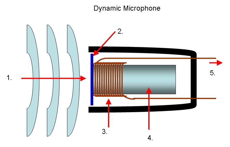
The mics here are dynamic microphones. The word "dynamic" refers to the mechanism inside: a small, lightweight diaphragm is attached to a coil of fine wire, and that coil sits inside the field of a permanent magnet. When sound waves push on the diaphragm, the diaphragm moves, which moves the coil, which moves inside the magnetic field. A coil moving in a magnetic field generates an electrical current. (This is the same principle, in miniature, that makes generators and electric motors work.)
The working parts of a dynamic microphone
1. Acoustic energy (the incoming sound wave) 2. Diaphragm (a thin membrane that vibrates when sound hits it) 3. Voice coil (a coil of fine wire attached to the back of the diaphragm) 4. Magnet (a permanent magnet sitting inside the coil) 5. Output wires (the two signal wires carrying the small voltage out to the XLR cable)
One thing the image doesn't show: the third connection inside an XLR cable, the ground. We'll meet it in section 4 when we look at the cable itself. The ground doesn't connect to the diaphragm-coil-magnet assembly the way the two signal wires do; it connects to the mic body and the cable shield, and its job is electrical safety and noise rejection. For now, the two wires in the image are the two that carry your sound.
Notice that the mic itself doesn't need power to do this. The energy that makes the electrical signal comes from the sound itself, transferred mechanically through the diaphragm and the coil. This is why a dynamic mic just works the moment you plug it in.
Dynamic mics have characteristic strengths. They're rugged (the moving parts are simple and not delicate). They handle loud sources well without distorting. They have a clear, present sound that flatters voices and many instruments. They're affordable and reliable enough that they end up on stages and in studios all over the world. The Shure SM57 and SM58 are the two most-recorded microphones in history, and both are dynamics.
They also have characteristic limits. Because the diaphragm has a coil and magnet attached to it, it's relatively heavy compared to other mic designs, and it doesn't respond to extremely fast or quiet sound details as faithfully as some other mic types. For most of what you'll do, that limit doesn't matter. The dynamic is the right tool. A different transducer type, the condenser, handles those finer details; it's worth knowing when to reach for each.
2.2 · Reading a mic's specs
Every microphone manufacturer publishes a spec sheet for each model: a single-page document that lists what the mic is, what it does, and how it does it. Some of the contents are practical numbers (weight, dimensions, what connector it uses). The two parts that tell you about the sound of the mic are two charts: the polar pattern, which shows what directions the mic listens to, and the frequency response, which shows which parts of the audio spectrum the mic emphasizes. Learning to read both is how you make sense of why two mics from the same manufacturer, that look almost identical from the outside, end up sounding different and getting used for different jobs.
Both mics here come from this family. The SM57 and the SM58 share the same internal cartridge, the same cardioid polar pattern, and the same chassis design. What separates them is the frequency response tailoring, which the spec sheets make explicit.
The polar pattern
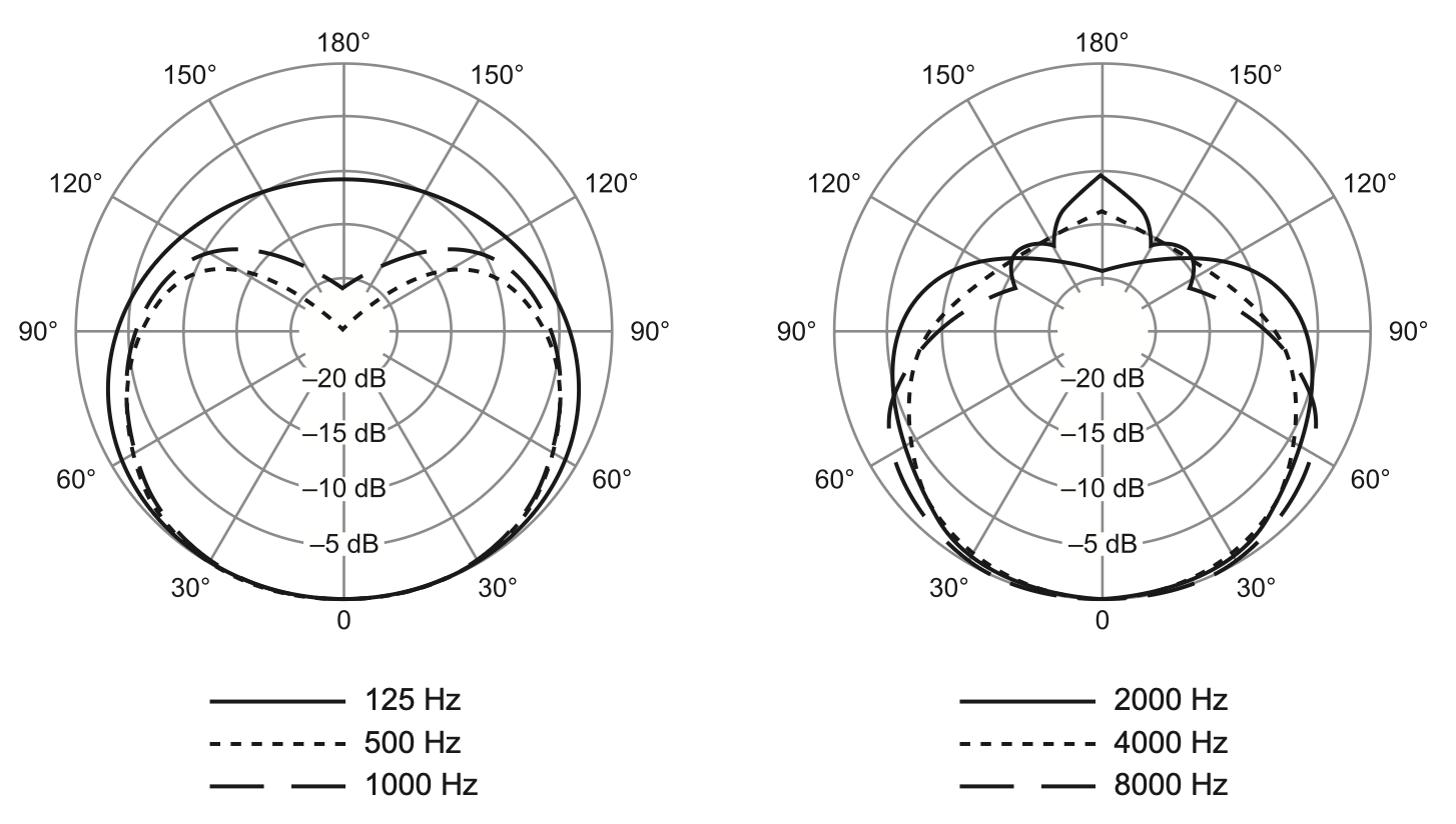
A polar pattern chart shows what a mic picks up from every direction around it. You can think of it as a top-down map of the mic's hearing. The mic sits at the center. The angle around the chart tells you where the sound is coming from: 0° at the bottom is directly in front of the mic (where you'd point it at your source); 90° and 270° are the two sides; 180° at the top is directly behind the mic. The concentric rings, labeled in dB going outward, tell you how loud the mic picks up sound from that angle.
Cardioid polar pattern (SM57 and SM58 share this pattern)
The curve traced on the chart is what the mic actually does. Reading the plot above: at 0° (directly in front), the curve sits at the outermost ring, which means the mic is most sensitive there. That's full pickup. As you move around toward 90° (the side of the mic), the curve pulls inward, sitting somewhere between the -5 and -10 dB rings depending on frequency. The side of the mic picks up sound, but less strongly than the front does (about a third to half as loud, roughly). Keep going around to 180° (directly behind the mic) and the curve pinches almost to the center: at -20 dB or beyond, the rear of the mic is barely picking up anything at all. This shape, full in front, reduced at the sides, near-zero behind, is what cardioid means.
You'll notice the chart actually shows several curves at once, one for each frequency the manufacturer measured (125, 500, 1000, 2000, 4000, 8000 Hz). The shape isn't perfectly identical at every frequency: at very low frequencies the mic picks up a bit more from the rear than it does at mid frequencies; at very high frequencies the pattern can get a little narrower in front. But all of these curves are recognizably the same cardioid shape. For our purposes, "cardioid" is the right name for what this mic does at any frequency you'd care about.
The operational consequence is simple: point the front of the mic at the sound you want, and put what you don't want behind it. If a noisy fluorescent fixture overhead, a classmate's whispering, or the room's general background wash is behind the mic while your source is in front, the mic rejects them. If they're in front and your source is behind, the mic captures the unwanted material and rejects your source. Mic placement is half of getting a good recording.
The frequency response
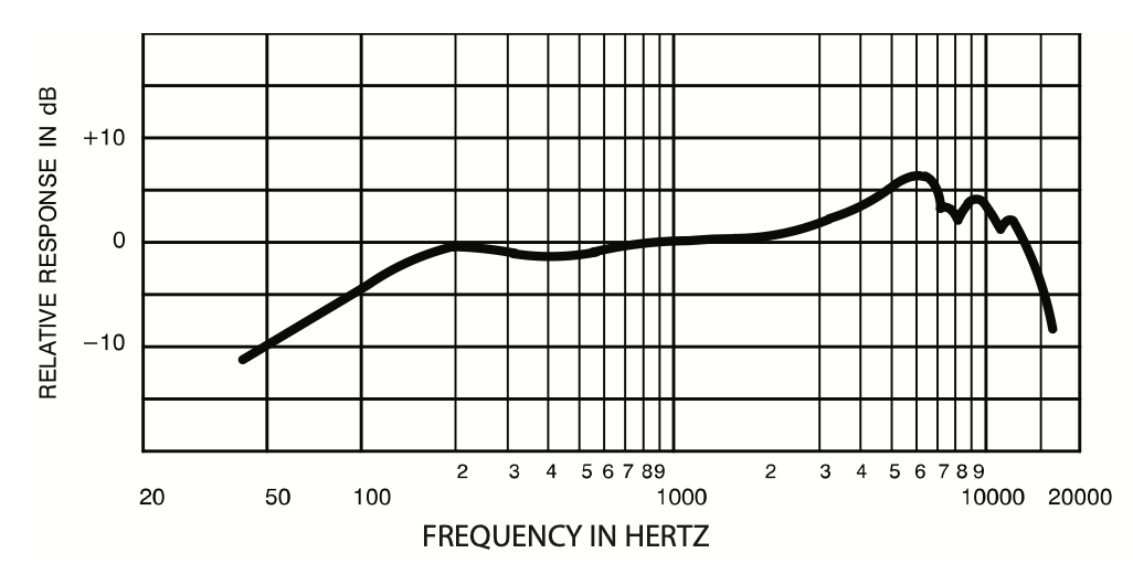
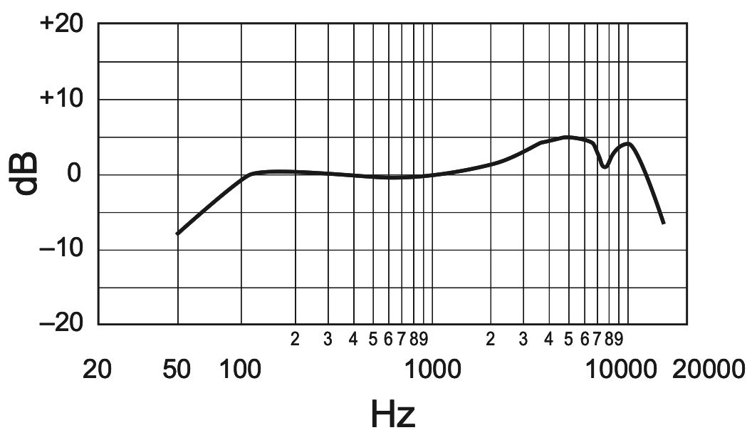
The frequency response chart shows which parts of the audio spectrum the mic emphasizes and which parts it de-emphasizes. The horizontal axis is frequency in Hz, running from low (around 20 Hz, the bottom of human hearing) on the left to high (around 20,000 Hz, the top of human hearing) on the right, on a logarithmic scale so equal distances on the chart correspond to equal musical intervals. The vertical axis is sensitivity in dB, relative to a flat reference of 0 dB. A curve that sits at 0 dB across the whole chart would mean the mic responds equally to every frequency. A curve that rises above 0 at some point means the mic emphasizes that part of the spectrum; a curve that falls below means the mic de-emphasizes that part.
SM57. The low end has a long rolloff: the curve drops from 0 dB at around 200 Hz all the way down to -12 dB at 45 Hz. Through the mids the curve sits near 0 dB. Starting around 2 kHz it climbs into a presence peak, reaching about +6 dB at 6 kHz: an emphasis in the upper-mid range where things like the snap of a snare drum, the bite of a guitar amp, and the consonants of a speaking voice all live. From there the curve has a distinctive wobble before rolling off: down to +4 dB at 7 kHz, +3 dB at 8 kHz, back up to +5 dB at 9 kHz, then the high end drops away. The SM57's spec sheet describes this curve as "tailored for drums, guitars, and vocals," and you can see what tailoring means: it's the shape of this curve, designed to flatter the things this mic gets pointed at.
SM58. Shorter rolloff at the bottom: the curve reaches 0 dB at around 100 Hz and only drops to -9 dB by 50 Hz. Through the mids the curve sits flat, like the SM57. A gentle climb from 1 kHz up to a presence peak of +5 dB at 4 kHz. Then a distinctive feature: a steep dip at 7.5 kHz that briefly returns to 0 dB before climbing back up to +5 dB at 9 kHz, then the high-end rolloff. The SM58's spec sheet calls this "tailored for vocals, with brightened midrange and bass rolloff." The bass rolloff is part of why this mic works well for singers: when a singer holds a cardioid mic close to their mouth, low frequencies get artificially boomy from a thing called proximity effect, and the SM58's shorter low-end extension helps compensate.
Same family of mic, two different tunings. Both share the cardioid pattern, the flat midrange, and a presence peak in roughly the same upper-mid region. What's different is the low end (the SM57 extends lower, the SM58 reaches flat sooner) and the shape of the high end (the SM57 has a wobble after its peak; the SM58 has a sharp dip-and-recovery). The SM57 is built for instruments that have musical content down low, like kick drums and guitar cabinets. The SM58 is built for the human voice, where the low-end shaping helps with proximity effect and the high-end shaping helps with vocal clarity. The spec sheets are showing the same kind of intentional design choices, expressed as two different curves.
What to take away
Every mic has both a polar pattern and a frequency response. Reading those two charts is how you learn what a mic is built to do, before you ever plug it in. Those same charts shift for other kinds of mics (condensers with different sensitivities, mics with omni or figure-8 polar patterns), and reading the differences is how you tell them apart.
3 · The mic-level signal
When the mic's coil moves and generates electricity, the voltage it produces is tiny. We're talking about a few thousandths of a volt, sometimes less. This is a category called mic level, and it's the smallest standard signal level you'll meet in audio work.
Mic-level signals are weak because the energy available to generate them is small. A diaphragm the size of a fingernail can only move so much, and the magnetic field can only induce so much voltage in the coil. To get a usable signal out of that, the mic-level signal has to be amplified, by a lot, before it's strong enough to be turned into digital audio. That amplification happens inside the audio interface. We'll get there in section 5.
Two consequences flow from mic level being weak, and they shape almost everything else in the chain:
First, weak signals are vulnerable to noise. Any electrical interference picked up between the mic and the interface (from power cables, fluorescent lights, computer monitors, radio) adds to the signal you actually want. If the interference is loud relative to your mic signal, you've recorded the interference as well as the source. This is why mic cables are built the way they are, and it's the topic of the next section.
Second, weak signals need amplification before they're useful. The interface contains a circuit called a preamplifier, or preamp, whose only job is to take that small mic-level voltage and boost it up to a much larger signal called line level. (Line level is the signal level your computer expects, and the level most other audio gear runs at internally.) The knob you'll turn to set how loud a mic comes through, called the gain, is the control for that preamp.
A note on the term "level"
In audio, "level" is used in at least two different ways. You'll hear it used to refer to volume ("the bass level is too high"), and you'll hear it used to refer to signal type ("the mic level is too small for a line input"). Both are correct usages; context tells you which one is meant. When this reading says mic level, instrument level, or line level, it's always referring to the second meaning: the standard category of signal that a piece of gear puts out or expects.
4 · The XLR cable
The cable that runs between a microphone and an audio interface is called an XLR cable, after the three-pin connector at each end. The connector locks into place with a small spring-loaded latch (you'll feel it click; to release it, press the small tab on the side of the connector and pull). The lock matters because a mic cable that gets pulled out mid-take is the kind of small disaster the design is meant to prevent.
What makes an XLR cable different from, say, the cable that plugs your headphones into a phone is what's inside. An XLR carries three conductors (three separate wires) where a headphone cable carries two or three depending on the design.
Inside an XLR cable, two of the three wires carry the audio signal, and the third is a ground (a shield wrapped around the other two). The two signal wires carry the same audio, but one of them carries it flipped upside down compared to the other (the technical term for this is phase: when two copies of a signal are flipped this way, they're said to be out of phase). So if wire A has the waveform going up, wire B has the same waveform going down by the same amount. Two copies of the signal, one of them inverted.
The trick of a balanced cable. Noise picked up along the run arrives on both wires the same way; the interface flips wire B upside down and sums it with wire A; the signal (flipped twice, so now in phase) doubles, and the noise (flipped once, so now out of phase) cancels.
When the cable picks up interference along its run (electromagnetic noise from a fluorescent light fixture overhead, say), the interference arrives on both wires equally, in the same direction. So at the far end of the cable, the interface sees:
Wire A: signal + noise
Wire B: inverted signal + the same noise
At the receiving end, the interface flips wire B upside down and sums the two wires together. The signal doubles. The noise cancels. Noise gone, signal twice as strong. This is what people mean when they call XLR cables balanced.
Pause
Why summing waves cancels them or doubles them
The cancellation and doubling that make balanced cables work are not specific to cables. They're properties of how waveforms add. When two waveforms get summed together (in any medium: in a cable, in the air, in a mixer, on a track in an audio editor like Audacity), the rule is the same: at every moment in time, you add the two values to get the sum.
If the two waveforms are in phase (both going up at the same time, both going down at the same time), every moment of one adds to a matching moment of the other. The peaks line up with peaks, the troughs with troughs. The result is the same waveform, twice as tall.
If the two waveforms are out of phase (one is the upside-down copy of the other: where A goes up, B goes down by the same amount), every moment of one adds to a matching opposite moment of the other. Peak plus trough equals zero, at every point. The result is silence.
Two identical waves sum to a doubled wave; a wave and its upside-down copy sum to silence.
A balanced cable engineers this principle to its advantage. When the interface flips wire B upside down before summing the two wires, two things happen at once. The signal, which had been carried as two opposite copies (out of phase), now arrives as two matching copies (in phase) and sums to double. The noise, which had been carried identically on both wires (in phase), now arrives as two opposite copies (out of phase) and sums to silence. The same flip-and-sum does both jobs, because phase is what tells the math which case it's in.
The practical upshot is that XLR cables can run long distances (50, 100 feet or more) carrying small mic-level signals without picking up audible noise. In a small home setup, where cables stay short, the protection isn't strictly necessary. But this is how every professional audio environment is wired, and it's the reason XLR is the standard mic cable.
5 · The audio interface
The audio interface is the box on your desk that the mic cable plugs into, and the box that connects to the computer over a USB cable. It's where the signal stops being analog (continuous electrical voltage) and starts being digital (a stream of numbers). The interface has three jobs, in order:
Amplify the mic signal. The preamp boosts mic level up to line level. The gain knob controls how much amplification. (If you've already glanced at the Behringer's input label, "Mic/Line 1," that's not a typo: the input accepts either a mic-level signal that needs preamp boost, or a line-level signal that's already at line level and just passes through.)
Convert analog to digital. The analog-to-digital converter (ADC) samples the now-amplified signal many thousands of times per second.
Send the data to the computer. Over a USB cable, the stream of numbers arrives at the computer's audio input. From there, any program that listens to that input can read it: Audacity, QuickTime, Ableton, or the system's own recorder. The interface delivers the signal to the computer; the software you choose decides what to do with it.
The interface also runs the reverse path for playback: it takes digital audio coming from the computer, converts it back to analog through a digital-to-analog converter (DAC), and sends it out to your headphones or speakers.
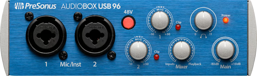
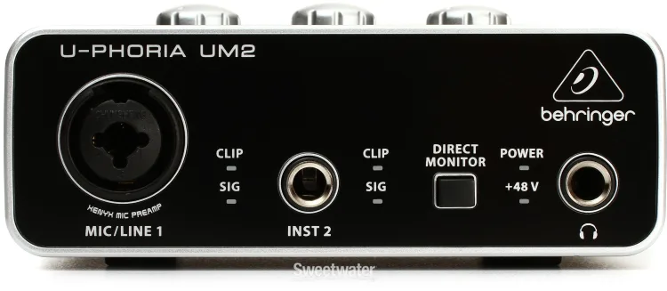
Two common entry-level interfaces stand in for the category here: the PreSonus AudioBox USB 96 and the Behringer U-Phoria UM2. Different interfaces lay out their controls differently. The features themselves are universal; the physical layout is the manufacturer's choice. Once you can find the universal features on any interface, you can sit down at any setup.
PreSonus AudioBox USB 96
Behringer U-Phoria UM2
Two interfaces, two layouts
Source: Sweetwater product listings (manufactured by PreSonus and Behringer)
Look at both interfaces and you'll find the same set of controls, even though they're positioned, labeled, and counted differently:
Inputs. Both interfaces have at least one combo jack on the left side: a connector that physically accepts either an XLR plug (for a mic) or a 1/4" plug (for a higher-level signal). The PreSonus has two combo jacks, both labeled Mic/Inst, meaning each one can take a mic or an instrument signal. The Behringer has one combo jack labeled Mic/Line 1 (mic or line-level signal) and, next to it, a dedicated 1/4" jack labeled Inst 2 for instruments only. This chain plugs an XLR mic into the leftmost input on either interface. The labels "mic," "line," and "instrument" name distinct signal types, worth knowing as you branch out beyond the basic chain.
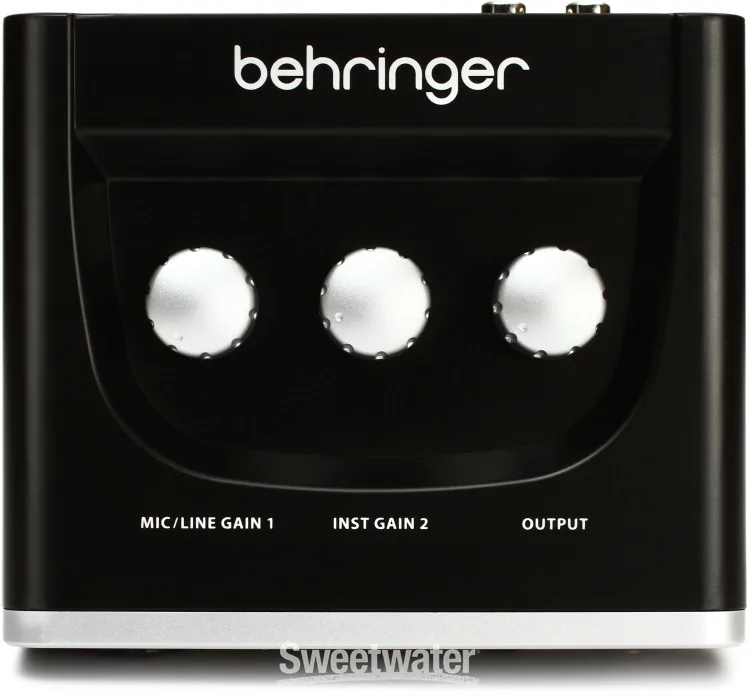
Gain knob for each input. The gain knob is the preamp control: it sets how much the mic-level signal gets amplified before the ADC sees it. On the PreSonus, two silver knobs sit on the front panel, one per channel, each marked 1 or 2, with Inst and Mic labels around the knob and a numeric scale from -10 to +30 dB. The Inst/Mic labels are rough guideposts for where each signal type typically sits; for a mic recording you'll usually end up somewhere in the lower part of the range. On the Behringer, the gain knobs are on the top of the unit, not the front: Mic/Line Gain 1 for the combo jack and Inst Gain 2 for the instrument jack.
Clip indicator for each input. The clip indicator is a red LED that lights up when the signal coming through the preamp exceeds the digital ceiling, the point at which clipping begins. On the PreSonus, the LED is integrated into the gain knob: a red dot labeled Clip just to the right of each gain knob lights up when that input is hitting its limit. On the Behringer, each input has a pair of stacked LEDs to the right of the jack: Sig (lights up when the input is receiving any signal at all) and Clip (lights up when the signal is clipping). Same diagnostic in two layouts.
Phantom power. Phantom power is a +48 V DC current that travels up the XLR cable to power a condenser mic's electronics (condensers need it; the dynamic mics here don't, and ignore it). On the PreSonus, the control is a red front-panel button labeled 48V, with a red light when it's on. On the Behringer, the switch is on the back (labeled +48V, with off/on positions), and a small +48V indicator on the front lights up when it's active. You can leave it off; it does no harm if it's already on, since dynamic mics don't respond to it.
Direct monitor control. The two interfaces handle this differently in a way worth understanding now. The Behringer has a square button labeled Direct Monitor: pressed in, the interface routes the incoming signal directly to the headphones with no latency; released, the headphones hear only what's coming back from the computer (with a small round-trip delay). It's a binary switch. The PreSonus has a knob labeled Mixer with Inputs on one side and Playback on the other: it sets a continuous blend between the two, so you can dial in any ratio of live-from-the-mic to back-from-the-computer in your headphones. The same need (hearing the mic without latency, instead of waiting for it to round-trip through the computer) gets solved with a switch on one interface and a continuous blend on the other.
Headphone output. Both interfaces have a 1/4" headphone jack on the front. The PreSonus has a dedicated Phones knob next to its main output knob, so headphone volume is controlled independently of the outputs that go to speakers or other gear. On the Behringer, headphone level is controlled by the Output knob on top of the unit, which also controls the level going to the rear outputs; one knob controls both destinations.
If you're on a Behringer
The Behringer's gain knobs are on the top of the unit, behind the front panel. There are three: Mic/Line Gain 1, Inst Gain 2, and Output. The first two control how much amplification each input gets. The Output knob controls the level going to your headphones and speakers.
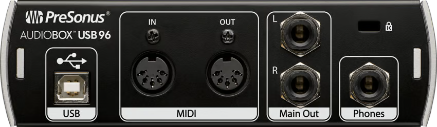
The back of an interface holds the connections: the USB cable to the computer, the output jacks that feed studio monitors or other gear, and (depending on the model) MIDI ports or the phantom power switch.
PreSonus back
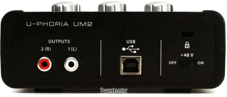
Behringer back
Two backs, again similar but not identical
Both backs have a USB-B port (where the cable that goes to the computer plugs in) and a Kensington security slot. After that they diverge. The PreSonus has two TRS output jacks (the same kind of jack a 1/4" cable plugs into, balanced like the XLR cable in section 4) for connecting to studio monitors, plus a pair of MIDI ports for controllers and synthesizers. The Behringer uses RCA jacks (the round, plastic-rimmed connectors common on consumer audio gear; unbalanced, meaning they don't have the noise-rejecting trick the XLR and TRS cables use) for its outputs, has no MIDI, and houses the +48V phantom power switch back here instead of on the front.
6 · Why audio interfaces vary so much in price
The PreSonus AudioBox USB 96 and the Behringer U-Phoria UM2 both retail for about $100. Look at Sweetwater's audio interface catalog, though, and the price range runs from around $50 at the bottom to over $7,000 at the top. Hosken's Introduction to Music Technology calls out the same range: from a few hundred dollars for a simple interface to about $1,000 for a midrange unit to over $10,000 for a high-end studio system. What changes across that range?
More expensive doesn't automatically mean better-sounding for what you're doing. Hosken puts it well: "price is often some sort of indicator of quality, though it is as uneven an indicator for audio interfaces as it is for cars or refrigerators." A $100 interface from a reputable manufacturer can produce recordings indistinguishable from a $1,000 one for many situations. What expensive interfaces buy you is some combination of more inputs and outputs, higher-quality components, additional features for specific workflows, and (sometimes) brand cachet. Several dimensions of variation cluster together as price climbs.
Channel count (I/O). The biggest single driver. Both interfaces here are 2-in / 2-out: two inputs come in, two outputs go out. If you want to record a four-piece band live (drums alone might want six or eight mics), you need an interface with at least that many simultaneous inputs and preamps. Step up to mid-range and you'll see 4-in / 4-out, 8-in / 8-out, and (in flagship units) 18-in / 20-out or higher. Most of the price climb from $100 to $500 is paying for more channels.
Preamp count and character. Each mic input needs its own preamp circuit, so more inputs means more preamps; that's part of the channel-count story. Beyond count, some interfaces are designed around a particular preamp sound: the warmth of a vintage tube preamp, the punch of a 1970s console, the transparency of a modern boutique design. Universal Audio's Apollo line, Solid State Logic's SSL series, and Neve's interfaces all sell partly on the strength of their preamp character. The standard solid-state preamps in interfaces like these are fine; preamp character becomes a creative tool once you're recording the kinds of musical sources where its color makes a perceptible difference.
Conversion quality (ADC/DAC). Bit depth and sample rate matter here. The two interfaces here sit at the standard end: one runs 24-bit at up to 96 kHz, the other 16-bit at 48 kHz. Both are perfectly serviceable. Higher-end interfaces push further: 32-bit, sample rates up to 192 kHz or 384 kHz, with converters designed for wider dynamic range (the gap between the quietest detail the converter can resolve and the loudest signal it can handle without clipping) and lower self-noise. The gain from a $2,000 converter over a $100 one is real but small, and audible mainly on sources that are themselves very quiet and very dynamic (a solo voice in a treated room, an unaccompanied acoustic instrument).
Connectivity and latency. Latency is the round-trip delay described in section 5: how long it takes a signal to leave the mic, reach the computer, and come back to the headphones. Faster connection protocols and better-engineered drivers cut that delay. Both interfaces here use USB 2.0 (the slower, older USB), which is fine for the work here because direct monitoring sidesteps the latency problem entirely. Mid-range interfaces often use USB-C; high-end interfaces use Thunderbolt (much faster, much lower latency) or PCIe (the interface installs directly inside the computer). Below about 5 milliseconds of round-trip latency, you can monitor through the computer with plug-in effects running in real time without it feeling lagged. That's a workflow entry-level interfaces like these don't enable, and a real reason to spend more.
Onboard DSP. Some higher-end interfaces include their own processors (the Apollo line and the SSL 2+ are two examples) that run audio effects (compressors, EQs, reverbs, even amp simulations) directly on the interface, before the signal ever reaches the computer. This is how you get plug-in effects with near-zero latency. Entry-level interfaces like these have none of this; any processing happens inside your DAW after the fact.
Digital I/O and expansion. Look at the back of a $1,000 interface and you'll see connectors entry-level interfaces don't have: ADAT (an 8-channel optical digital connection for adding eight more preamps via an external preamp box), S/PDIF (a stereo digital connection for routing audio digitally between gear), AES/EBU (the professional version of S/PDIF, carried over XLR cables), MADI (up to 64 channels of audio over a single cable, used in large studios), and word clock (a timing reference that keeps multiple digital devices sample-accurate together). These are the connections that let an interface scale up beyond its built-in channel count, by connecting to other digital gear.
Both interfaces here are entry-level by design. A 2-in / 2-out interface, a few hundred dollars cheaper than the next tier up, is exactly enough for the work here: one source recorded at a time, prepped into a sample library, used in a DAW. The features that justify a $500 or $1,000 or $5,000 interface are real, but they answer questions a setup like this doesn't need to answer. Once you can read a spec sheet (the manufacturer's, or a retailer's like Sweetwater's), you can match an interface to a workflow rather than pricing alone.
Vocabulary
Signal flow
The path that sound takes from acoustic source to stored file. Every recording setup has one. The basic recording chain is the most common version of it.
Recording chain
The specific signal flow described here: a dynamic mic and a computer, connected through an audio interface, with an XLR cable between mic and interface and a USB cable between interface and computer.
Transducer
A device that converts one kind of energy into another. A microphone converts acoustic energy (air pressure) into electrical energy (voltage). A speaker does the reverse.
Dynamic microphone
A microphone that uses a moving coil and a magnet to generate its signal. Rugged, no power needed, common on stages and in studios. The kind of mic this reading is built around.
Cardioid
The pickup pattern of most dynamic mics, including the SM57 and SM58. Most sensitive in front, less sensitive at the sides, rejects sound from behind. The shape of the response curve resembles a heart, which is where the name comes from.
Polar pattern
A chart on a microphone's spec sheet that shows what directions the mic picks up sound from. Concentric rings = sensitivity in dB; angles around the chart = direction relative to the front of the mic. Cardioid is one polar pattern; others include omni and figure-8.
Frequency response
A chart on a microphone's spec sheet that shows which parts of the audio spectrum the mic emphasizes and which it de-emphasizes. Horizontal axis = frequency in Hz (low to high); vertical axis = sensitivity in dB relative to a flat reference. A curve above 0 dB means emphasis at that frequency; a curve below means de-emphasis.
Presence peak
A bump in a mic's frequency response in the upper-mid range (typically around 3 to 8 kHz) that emphasizes consonants, snare snap, and guitar bite. Most dynamic mics designed for live and studio work have one.
Proximity effect
The boost in low frequencies that happens when a directional mic (like a cardioid) is held very close to its source. Vocal mics like the SM58 are designed with a built-in low-frequency rolloff to compensate.
Mic level
The very small signal level that comes out of a microphone. Measured in thousandths of a volt. Needs amplification (by a preamp) before it's useful.
Line level
The standard signal level that audio gear uses internally, and that your computer expects. Much larger than mic level. The preamp's job is to lift mic level up to line level.
Preamp (preamplifier)
The circuit inside an audio interface that boosts mic-level signals up to line level. The gain knob is the control for it.
Gain
The knob on an audio interface that sets how much the preamp amplifies the incoming signal. The control that decides whether a recording is clean.
XLR cable
The standard cable for mic-level audio. Three-conductor, balanced. Carries the signal as two opposite-polarity copies, which lets the interface cancel out picked-up noise at the far end.
Balanced cable
A cable design that carries two opposite-polarity copies of the signal. At the receiving end, one copy is flipped upside down and summed with the other: the signal (now in phase) doubles, the noise (now out of phase) cancels. XLR is the most common balanced cable type.
Phase
The position of a signal in its cycle of going up and down. Two copies of a signal that move together (both going up at the same time, both going down at the same time) are in phase. Two copies where one is flipped upside down relative to the other (one going up while the other is going down) are out of phase. When out-of-phase copies are summed, they cancel; this is the principle a balanced cable uses to reject noise.
USB cable
The cable that carries digital data between the audio interface and the computer. Doesn't carry audio in the analog sense; carries the stream of numbers the ADC produces.
Audio interface
The hardware box that plugs into the computer over a USB cable and handles the conversion between analog audio and digital audio. Houses the preamp, the ADC, and the DAC.
ADC
Analog-to-digital converter. The circuit inside the interface that turns an analog electrical signal into a stream of digital samples. The sample-rate and bit-depth choices shape what the ADC produces.
DAC
Digital-to-analog converter. The reverse circuit: turns digital audio coming from the computer back into an analog signal for playback over headphones or speakers.
Clipping
The harsh distortion that happens when a signal exceeds the digital ceiling (0 dBFS, the maximum a digital signal can represent). Unrecoverable in editing. The clip indicator on an audio interface lights up when this is happening.
Direct monitoring
An audio-interface feature that routes the incoming signal straight to the headphone output without going through the computer. Avoids the small but distracting delay of round-tripping the signal through the recording software.
Monitor mix
The knob on an audio interface that blends the live input signal with the computer playback in your headphones. Turn it toward "input" when you want to hear what the mic is picking up; toward "playback" when you want to hear what's already in the recording software.
Latency
The round-trip delay between a sound entering an interface and coming back out of the headphones after a trip through the computer. Measured in milliseconds. Direct monitoring avoids it by routing the live signal around the computer entirely. Faster connection protocols (Thunderbolt, USB-C) lower it; older USB 2.0 interfaces have more of it.
DSP
Digital signal processing. The audio computations a computer (or a dedicated processor inside an interface) performs on a digital signal: EQ, compression, reverb, modeling, etc. Higher-end interfaces include onboard DSP that runs effects without taxing the computer.
Digital I/O
Inputs and outputs that carry audio as a digital signal rather than as an analog voltage. Common types: ADAT (8 channels of optical audio over a single cable), S/PDIF (2 channels of digital audio over RCA or optical), AES/EBU (the professional version of S/PDIF over XLR), MADI (up to 64 channels over a single cable). Higher-end interfaces include digital I/O for expanding their channel count by connecting to other digital gear.