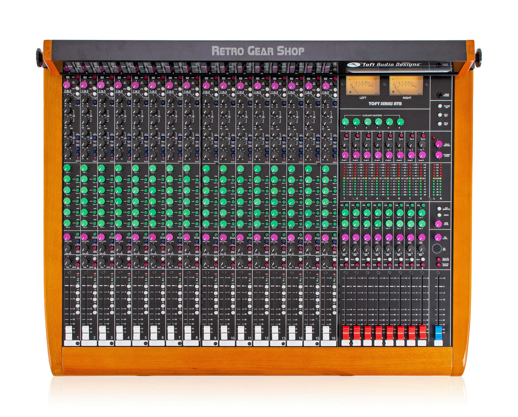
Photo via Retro Gear Shop.
In the basic recording chain, the destination of every signal flow is an audio interface: a small box, one or two inputs, plugged into the studio Mac, getting one signal at a time into the digital audio workstation (the recording software running on the computer; from here on I'll use the shorthand DAW for the whole flow from the audio interface into whatever software is doing the recording). That works when there's one mic and one sound to record. It stops working the moment there are seven mics on stage and the engineer needs to balance, EQ, and route each one independently to multiple destinations at once. The mixer is what gets used in that situation. It doesn't replace the audio interface; in a studio setup the mixer sits between the mics and the interface. The mics plug into the mixer, the engineer shapes and combines the signals on the console, and the mixer's outputs feed the audio interface, which still gets the result into the DAW. The interface's role shifts from "the only routing point" to "the link between the analog console and the digital recording," and the mixer becomes where the engineering work actually happens.
That description fits an analog mixer, which is what's in our studio and what this reading covers. Every signal path on an analog mixer is a real voltage moving through physical circuitry; the mixer has no concept of digital audio on its own, which is why a separate audio interface is needed to get the output into a computer. A digital mixer is a different piece of equipment: its mixing, EQ, routing, and effects all happen as math on digital audio samples rather than as voltages through circuits. Most modern digital mixers (Behringer X32, Allen & Heath SQ, Soundcraft Si, Yamaha QL, and others) include the analog-to-digital conversion stage inside the same box as the routing, and connect directly to a computer over USB or ethernet. In that setup, the digital mixer is the audio interface; every channel on the console can become a recording input to the DAW without a separate interface in the chain. The routing concepts are the same across both kinds (channel strips, aux sends, subgroups, masters, inserts), so the work you do on our analog Toft transfers directly to any digital console you'll meet in the field. The differences are in feel, in how settings get saved, and in whether the math is happening in copper or in code.
A mixer (or console, or board, or desk: the words are interchangeable) is the piece of equipment in the middle of every multi-source audio workflow. Each source plugs into its own channel. Each channel has its own controls (level, EQ, routing, sometimes more). The channels combine into one or more outputs that go somewhere: speakers, headphones, a DAW.
The mixer's job is the same in every context: take many flows in, let the engineer shape each one, and send the combined result somewhere. What changes from context to context is what's connected at the input and where the output goes. Live sound and studio recording are two of those contexts. The hardware between them is the same hardware; the patching changes.
Our studio's console is the Toft Audio Designs Series ATB, designed by Malcolm Toft, who founded Trident Audio in 1972 and built consoles for studios that recorded David Bowie, Queen, Stevie Wonder, and many others. The Toft ATB is a modern descendant of that lineage: a smaller, more affordable design for project studios, but with the same channel-strip layout you'd find on a console in a commercial studio. Once you learn this one, the next one will feel familiar.
The board has three kinds of strips, arranged left to right:
Every input on the console is a vertical strip with the same set of controls, top to bottom. Learn one strip and you know all of them. Here's a single channel:
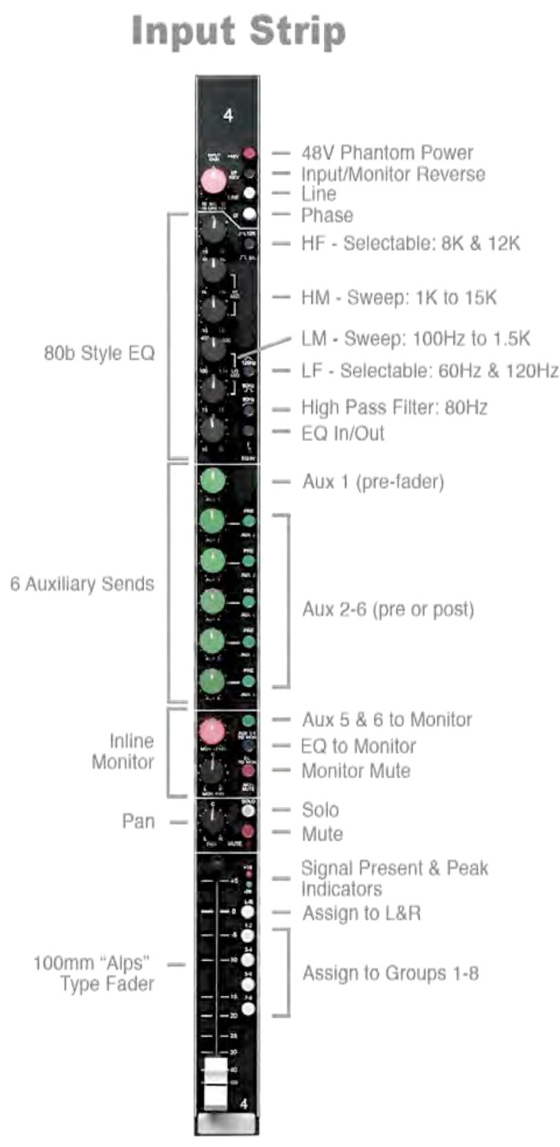
From top to bottom, the controls do this:
Input section. A button labeled +48V turns phantom power on (you met this earlier). A button labeled I/P REV (input reverse) swaps two signal paths inside the channel; we come back to it in section 3. A button labeled LINE switches between the mic input on the back and the line input on the back. A red knob labeled INPUT GAIN sets how much amplification the preamp applies. Same gain knob you set earlier to set peaks at -12 to -6 dBFS in an audio editor like Audacity; here it's setting the level going into the mixer's own internal flow.
Phase reverse and an 80 Hz high-pass filter. Two small switches. Phase reverse flips the polarity of the signal (sometimes needed when two mics on the same source are partially cancelling each other). The 80 Hz filter rolls off everything below 80 Hz, useful for cutting room rumble or wind on vocal mics.
You met phase earlier, inside the XLR cable: two wires carrying the same audio, one flipped upside down, summed at the interface so external noise cancels out (peak meets trough, the math collapses to silence). The phase-reverse button on the channel strip does the same flip operation, but here on the whole signal, on purpose. Two mics on the same source can sometimes produce signals that are partially out of phase with each other (some frequencies cancel, leaving the sound thin and hollow). Hitting phase-reverse on one of the two channels flips that channel's polarity and lets you check whether the sum gets stronger or weaker. Stronger means you'd been cancelling something; the flip fixed it. Weaker means leave the button alone.
Four-band equaliser. Four pairs of knobs. Each pair is a frequency control (which band of the spectrum to affect) and a boost/cut control (how much to change it). High, high-mid, low-mid, and low. Each band can boost or cut by 15 dB. The high and low are shelving (everything above or below a frequency moves together); the two middle bands are peaking (a bell curve centered on the chosen frequency). The whole EQ section can be switched into or out of the signal path with one button.
The EQ you used in an audio editor like Audacity () and the EQ on this channel strip do the same job: boost or cut specific frequency ranges of the signal. The surface is different. In an audio editor like Audacity, you click points on a curve and the software shapes the audio mathematically; on the console, you turn knobs and an analog circuit shapes the signal as the voltage flows through it.
The other difference matters more: where in the signal flow the EQ sits. The Filter Curve EQ in an audio editor like Audacity changes the audio data on the track when you click Apply (destructive: you can undo it during the session, but if you save and close, the change is permanent). The console's EQ shapes the signal as it passes through the channel strip on its way to the output. Whatever's plugged into the input (the mic on stage, the DAW playback at mixdown) keeps making the sound it was making; only the signal coming out of the channel is shaped. Turn the EQ knobs back to flat, or hit the EQ In/Out button, and the channel returns to passing the signal through unchanged. This is non-destructive: you can change your mind freely, take after take, without ever altering the source.
Six aux sends. Six green knobs, one per aux. Each one is a tap of the signal at this channel that goes out to a separate output on the back of the console (the AUX MASTERS jacks). The level of each tap is set independently of the channel's main fader. Aux 1 is permanently pre-fader (the tap happens before the fader, so the fader doesn't affect the aux level). Auxes 2 through 6 can be switched pre or post: pre-fader (independent of the fader) or post-fader (the fader controls them along with the main channel signal).
Think of the channel's signal as a river flowing left to right through the strip, from the input on top down to the fader and out into the master mix. The aux sends are taps along the river: small pipes that siphon off a copy of the water into a separate channel running somewhere else, without slowing the main flow. Each aux knob controls how much water its pipe carries; turn it down to zero and that pipe sends nothing.
The main flow doesn't change because of the taps. Whatever level you set on the channel fader, the signal arriving at the master mix is the same. The aux taps are parallel: they pull a copy off the main flow without subtracting from it. This is what makes one channel useful to many destinations at once. The vocal mic feeds the main mix (audience), and the singer's stage monitor (via Aux 1), and a reverb unit (via Aux 4), all simultaneously. One signal, many places, each at its own level.
Monitor section. A second smaller level control, labeled MON LEVEL, with its own MON PAN. This is a second input on the same strip, with its own way into the master mix, and it's the reason this console is called in-line. We'll unpack the monitor section in section 3.
Solo and mute. Two small buttons near the bottom. SOLO isolates this channel in the control-room speakers (the same solo you used in an audio editor like Audacity, but in hardware). MUTE silences the channel without changing the fader position.
Channel pan. A red knob that places this channel left or right in the stereo image.
Routing buttons. Beside the fader: L-R assigns this channel directly to the master mix; 1-2, 3-4, 5-6, 7-8 assign it to one of the four subgroup pairs (subgroups 1 through 8). The buttons are independent (any combination can be engaged), and the typical case is to use one or the other: L-R for a channel that goes directly to the mix, or a subgroup pair for a channel that wants to be grouped with others first. The pan knob decides the left-right split across whichever pair the signal arrives on.
Worked example. You have a mic plugged into channel 1, and you press the 1-2 button on that channel. The channel's signal is now routed to the subgroup pair 1 and 2 (subgroup 1 = left side of the pair, subgroup 2 = right side; odd-numbered sub on the left, even on the right). What happens next depends on the channel's pan knob.
With the pan knob in the centre: 50% of the signal goes to subgroup 1, 50% goes to subgroup 2. Pan all the way to the left: 100% of the signal goes to subgroup 1, 0% to subgroup 2. Pan all the way to the right: 100% to subgroup 2, 0% to subgroup 1. Anywhere in between is a smooth ratio (75/25, 60/40, etc.).
This is what people mean by a stereo bus: two subgroups treated as a left-right pair, with the channel pan knob acting as a level splitter between them. A bus is the point inside the console where many channel signals combine into one; the technical name for that combining operation is mixing (also called summing, which is more literal: the bus adds the channel signals together into one). Sub 1 is one bus, sub 2 is another; treating them as a pair gives you a stereo bus. The master mix works the same way at a larger scale, summing every channel routed to L-R into the final stereo program.
The fader. The main level control for this channel. Where the channel sits in the final mix. The scale beside it runs from minus-infinity at the bottom (fader all the way down, signal fully attenuated, no audio passing through) up past -40, -30, -20, -10, -5, through 0 (a thicker line, usually marked with a small notch), and up to +5 and +10 at the top. The 0 mark is called unity gain, or just unity: the fader is passing the signal through at the same level it came in at, with no change. Above unity, the fader amplifies the signal further (up to +10 dB on this console). Below unity, it attenuates: -10 dB cuts the signal level noticeably; -20 dB cuts it sharply; further down still and the signal is barely audible. The dB scale here is the same decibel scale you saw on the meters in an audio editor like Audacity, with the same warning behavior: small moves near the top of the scale do a lot, large moves near the bottom do relatively little.
Each strip's input and a few of its output jacks live on the back of the console. Looking at the rear panel for the first eight channels:
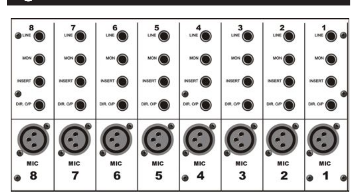
Five jacks per channel. Reading from the top down (the order they appear on the panel):
Earlier you met TRS as a cable with three conductors (tip, ring, sleeve), and saw two ways to wire it: balanced (tip = signal, ring = inverted signal, sleeve = ground), and unbalanced stereo (tip = left, ring = right, sleeve = ground).
On an insert: tip = send (the channel's signal going out to the outboard processor), ring = return (the processor's output coming back into the channel), sleeve = ground. The two signal conductors aren't a stereo pair and they aren't a balanced pair. They're a two-way loop: one carries the signal out, the other carries the processed signal back, on the same physical cable. The signal leaves the channel, runs out the tip, goes through whatever processor you've patched in, returns through the ring, and re-enters the channel further down the strip. This is what people mean when they say "insert send and return on a single TRS." One cable, two signals, opposite directions.
Cables wired this way are sometimes called insert cables: a TRS plug at one end, two TS plugs at the other (one labeled "send," one labeled "return"), so you can patch the loop into a piece of gear that has separate input and output jacks.
Both an insert and an aux send have a connector called "send" leaving the strip, and the word does different work in each case.
An aux send is a parallel branch. The aux pulls a copy of the channel's signal off at a tap point and routes it somewhere else. The main flow through the channel keeps going at full strength, untouched. Two signals end up in flight at the same time: the original on the channel, a copy out at the aux destination. Nothing comes back to the channel from an aux send (the copy will come back to the master section, however, via whatever destination it was sent to: for example, a reverb return blended into the master mix). (The river-with-taps diagram earlier in this section.)
An insert is a serial loop. The insert breaks the channel's signal path: the signal leaves the strip at the tip, runs through the outboard processor, and the processed signal comes back through the ring to take its place. While the loop is active, the original unprocessed signal is no longer on the strip. The whole round trip happens in real time, fast enough to feel instantaneous: the signal is being shaped continuously as it passes through the processor, with no audible delay between leaving the strip and coming back.
The rule of thumb for which audio effects belong on an insert and which belong on an aux send: if the effect replaces the signal, use an insert. If the effect adds something alongside the signal, use an aux send. Compressors, limiters, gates, de-essers, external EQs, and distortion all work on the signal itself, so they go on inserts. Reverb, delay, and the modulation effects (chorus, flanger, phaser) produce a separate wet stream that plays back alongside the dry, so they go on aux sends. There are exceptions in advanced use (parallel compression sets up a compressor on an aux send for deliberate blend; "insert reverb" exists for special cases), but the rule covers the great majority of decisions you'll make.
Every channel has its own copy of all five.
The Toft ATB is what's called an in-line console. The defining feature: every input strip carries two inputs at once, not one. There's the main input that travels down the big fader (set up in section 2): mic or line on the back, through INPUT GAIN, EQ, the fader, the routing buttons, out to L-R or a subgroup pair. And there's a second, smaller input that travels through the monitor section in the middle of the strip: a separate signal on the back at the MON jack, with its own level (MON LEVEL) and its own pan (MON PAN), routed to the master mix.
Both inputs can be active at the same time on the same strip, carrying two different signals to the master mix.
The label MON on the back of the console, and MON LEVEL on the front, both use the word monitor. The word isn't naming the studio speakers. It's naming the source: in the era of multi-track tape, "monitoring" a recorded track meant hearing the playback come back into the console alongside whatever was being newly recorded, so the engineer could keep checking the take against the previously-recorded layers. The MON jack on the back is that playback-return input.
At the top of every input strip is a button labeled I/P REV (input reverse). Press it, and the two inputs on that strip swap. Whatever was coming in the MIC or LINE jack now travels through the monitor section; whatever was coming in the MON jack now travels through the channel path with full EQ, aux sends, and the big fader. The most common use is at mixdown, when an engineer wants the full processing chain on the recorded track that had been coming back through the smaller monitor section during tracking.
To the right of the sixteen input strips sits the submaster section: eight narrower strips that handle group outputs, monitor returns, and effects returns.
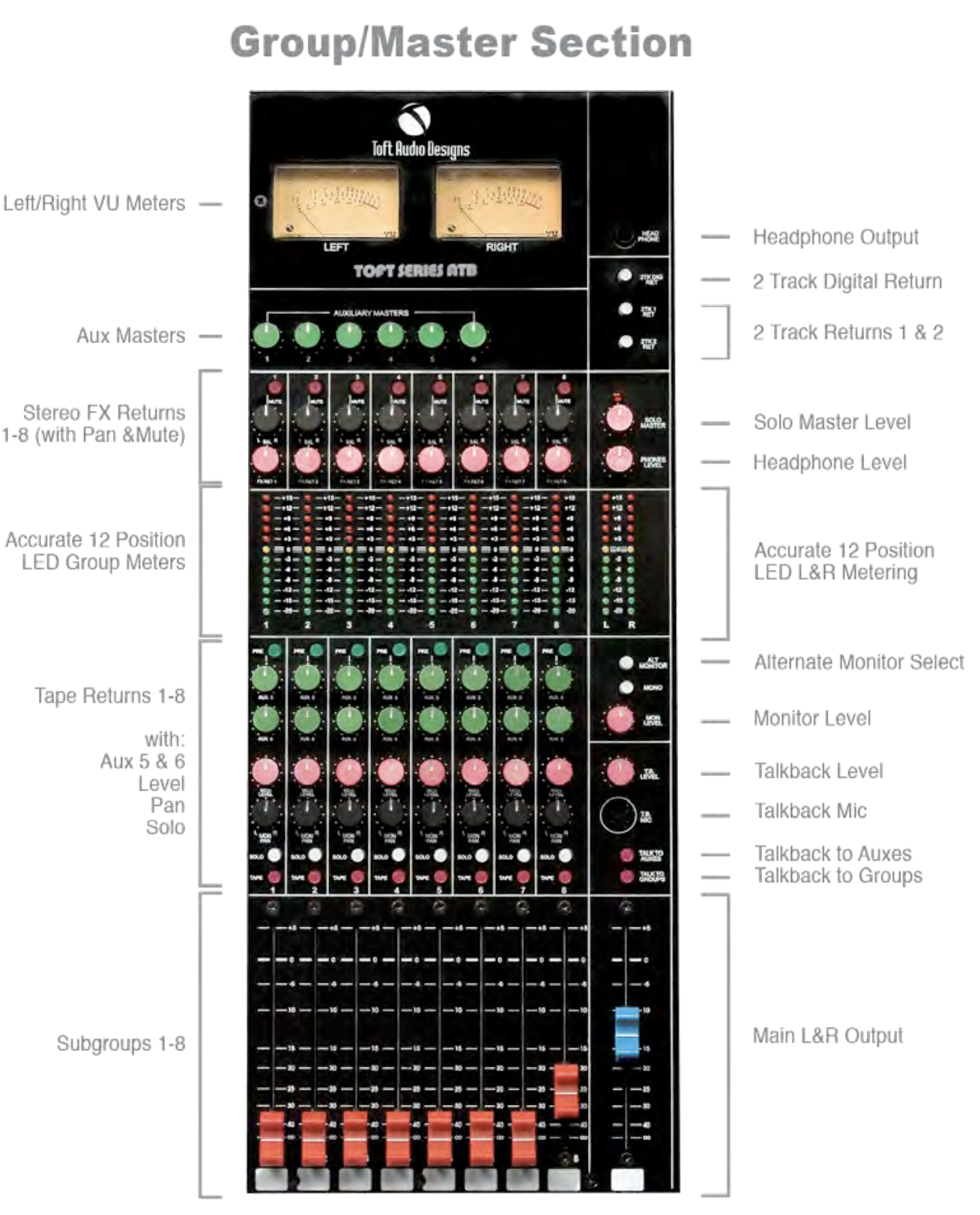
For this section, focus on the eight submaster strips that fill the left side of the photo. (The two rows of controls at the very top of the section, the L/R VU meters and the row of six green Aux Masters knobs, belong to the master section and are covered in section 5.)
Each submaster strip is built of four labeled sub-sections, top to bottom: a stereo effects return, a bargraph meter, a tape return, and at the bottom the subgroup fader.
A self-contained stereo input for a signal coming from an outboard audio effect unit (a reverb, a delay, a hardware processor), plugged in at the back of the console. Three controls plus a button, top to bottom:
Twelve segments running from -20 dBFS at the bottom to +15 dBFS at the top. Same dBFS scale as the meter in an audio editor like Audacity, with the same green / yellow / red zones. The meter shows the level of either the subgroup output going to the DAW, or the tape return coming back, depending on the TAPE switch in the section below.
The whole middle block of controls (PRE, AUX 5, AUX 6, MON LEVEL, MON PAN, SOLO, TAPE) is one named section. The label "Tape Return" describes what these controls do during playback, when the strip is monitoring the DAW's output coming back into the console. The same controls also work on the subgroup output going to the DAW: the TAPE button at the bottom of this section selects which signal the controls (and the bargraph above) are operating on.
Top to bottom inside this section:
AUX 5 and AUX 6, with PRE switch. The submaster strips each have two aux sends, sharing buses with channel auxes 5 and 6 (the callout below explains why). Use them to send the subgroup off to wherever a stage monitor or a headphone cue needs the whole sub-mix. The PRE button decides whether the tap happens before or after MON LEVEL.
An aux send is a bus: a single horizontal conductor that runs the length of the console, with every channel and submaster that wants to contribute connecting to it through its aux knob. Aux 5 is one bus; everything that turns up its aux 5 knob dumps a copy of its signal onto that bus, which ends at the Aux 5 Master in the master section and goes out the AUX MASTERS 5 jack on the back.
Making the submaster aux sends share buses with the channel aux sends (instead of introducing aux 7 and 8) keeps the bus count down. Each new bus would mean another conductor across the console, another Aux Master knob, another output jack on the back.
MON LEVEL and MON PAN. A red knob and a small black knob. This is the submaster's route into the master mix: MON LEVEL sets how much of the subgroup joins the master mix, MON PAN places it left-right in the stereo image. With MON LEVEL all the way down, the subgroup is heading only to the SUBMASTER OUTPUTS jack (the send to the DAW); turn it up and the subgroup also arrives in the master mix. The job of these two controls is the subgroup equivalent of the L-R button and channel pan on an input strip, but at the group level instead of the individual-channel level.
The labels on the front panel say MON, but the destination is the master mix, not the studio speakers. (Section 5 covers the master strip's MON LEVEL knob, which is a different control with a different job: the volume of the control-room speakers.)
SOLO. A white pushbutton. Press it to send just this submaster to the solo bus, muting the other submasters in the control room while you listen. Same job as the SOLO button on the input strip, applied at the group level instead of the channel level.
TAPE. A red pushbutton that selects the source for the whole middle section (bargraph, AUX 5 and 6, MON LEVEL and MON PAN, SOLO). Up: the live subgroup output, summed from whichever input channels routed here. Down: the playback coming back from the DAW through the MONITOR RETURNS jack on the back (covered later in this section). The name TAPE is a holdover from when those returns were a tape machine; most studios now use it to flip between "what's going to the DAW" and "what's coming back from the DAW."
A 100mm fader controlling the level of this subgroup's output at the SUBMASTER OUTPUT jack on the back: the level the DAW gets. It does not affect the subgroup's contribution to the master mix (which is set by the MON LEVEL above). The fader scale matches the input strip's: minus-infinity at the bottom, 0 (unity) marked with a thicker line, +10 at the top.
Recall the five routing buttons from section 2 (L-R, 1-2, 3-4, 5-6, 7-8). The L-R button assigns the channel directly to the master mix; the other four assign it to one of the four subgroup pairs. When several channels are routed to the same subgroup pair, their signals mix together in that subgroup (the summing operation from section 2's bus callout): the subgroup carries the combined output of every channel routed to it, with each channel's pan position deciding the left-right split between the two subgroups in the pair.
The canonical case is drums. Say four drum mics (a kick, a snare, and a pair of overhead mics for the cymbals and the overall kit) all route to subgroup pair 1-2. Kick and snare are panned center (each splits 50/50 between sub 1 and sub 2); the left overhead is panned hard left (100% to sub 1); the right overhead is panned hard right (100% to sub 2). The four channels become two combined signals on the subgroup pair, and the kit is now a single stereo group inside the console. From here, the kit travels onward together as a stereo pair: sub 1 carries the left side, sub 2 carries the right, and the controls on the two submaster strips set what happens to that stereo pair on its way out. The next callout walks where it goes.
From the subgroup, the combined signal goes to two places, each with its own control on the submaster strip:
The two destinations are independent. The DAW can get one level (set by the submaster fader), while the master mix gets another (set by the MON LEVEL). Neither has to follow the other.
So if four drum mics are routed to subs 1-2 only (channels with the 1-2 button engaged, L-R off), the kit reaches the DAW via the submaster faders and reaches the master mix via the MON LEVEL knobs. The submaster strip is doing the work of a stereo-pan-and-level control for the whole drum group on its way into the mix, with a separate fader for the DAW send.
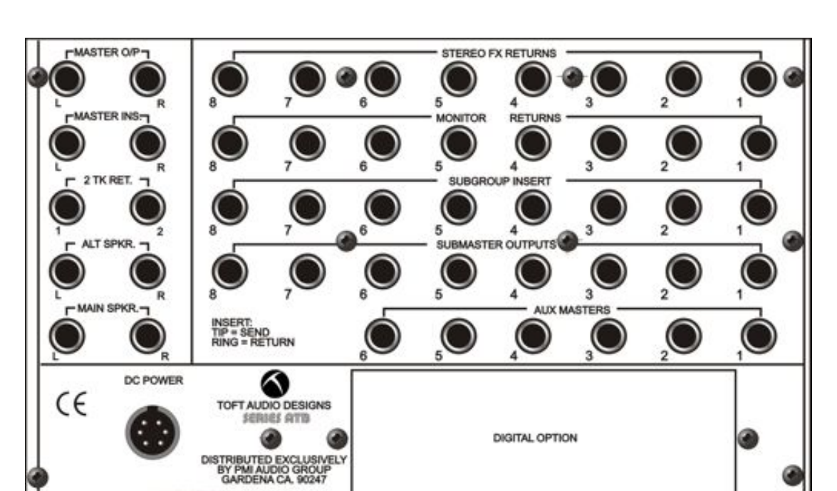
The submaster section is the right side of the panel. Top to bottom, the four rows of jacks are:
The bottom row of jacks (AUX MASTERS) and the left side of the photo (master outputs, master inserts, two-track returns, speaker outputs) belong to the master section, covered next.
One strip, on the far right of the console (the right third of the group/master photo from section 4, repeated here for reference):
The master section handles everything that affects the whole console rather than any single channel. Two rows of controls sit at the very top of the section, above the eight submaster strips from section 4; the master strip itself fills the column on the far right.
L/R VU meters. The two round needle meters at the very top, labeled LEFT and RIGHT. VU meters respond more slowly than peak meters: they average the signal over a short window, which makes them a better visual stand-in for perceived loudness than for instantaneous peaks. The needle moves with the music in a way the bargraph segments do not.
Aux Masters. Six green knobs in a row across the top of the section, one per aux send. Each aux send across the desk (the six on every input channel, plus auxes 5 and 6 on every submaster strip) feeds into one of these six masters; the Aux Master knob then sets the overall level of that aux's output before it leaves the back of the console at the corresponding AUX MASTERS jack. Think of each Aux Master as the master fader for one of the six parallel mixes the aux sends create.
The remaining controls run down the master strip on the far right of the section, top to bottom.
Headphone jack. A stereo headphone output (the round HEAD PHONE jack near the top of the strip). The engineer's headphones. The level for this jack lives a few controls down (see PHONES LEVEL below).
Two-track returns. Three pushbuttons that switch the control-room monitor over from the live mix to one of the 2-track return inputs: 2TK DIG RET (from the optional digital card), 2TK 1 RET, and 2TK 2 RET (analog). This is what you press when you want to A/B the mix you've recorded against the live mix coming out of the console.
A/B is a comparison move. You have two versions of the same audio, you switch between them (A, then B, then A again), and you listen for what changes. The two versions could be: the live console mix vs. the recorded version of that mix, two different masters of the same song, your mix vs. a commercial reference track, a "before" version of a mix vs. an "after" version with some processing applied.
The 2-track return buttons are the A/B switch built into the console. The live console mix is "A"; press a 2TK RET button and you're now hearing "B" (whatever is plugged into that return). Release the button and you're back at A. Press a different 2TK RET button and you're at C, the next thing under comparison.
The point of A/B-ing is that the ear has a short memory. It's hard to tell whether a mix sounds better or worse if you can't switch back and forth quickly. The button collapses the comparison into something you can hear in seconds, while the impressions are still fresh.
SOLO MASTER. A pink knob that sets the level of the solo bus in the control room. When any channel or submaster has its SOLO button engaged, this knob controls how loud the soloed signal plays in the monitors.
PHONES LEVEL. A pink knob that sets the headphone jack's level (the jack near the top of the strip). Separate knob, separate position, separate function from the monitor level a few controls down.
Master bargraph meters. A 12-segment L/R pair showing the final stereo output. The main metering reference: same dBFS scale as the meter in an audio editor like Audacity, same green/yellow/red zones. Faster response than the VU meters at the top of the section, useful for catching peaks the VU needles would smooth over.
The master section has two distinct outputs going to two different places. They both carry the master mix, but they diverge after the master fader, and the controls on either side don't affect the other.
The first output is MASTER O/P (L and R, balanced jacks on the back). This is the master mix on its way out of the console: to the DAW input, or to the front-of-house (FOH) amplifiers driving the audience speakers in a live show, whoever is capturing or carrying away the mix. The master fader at the bottom of the strip sets the level out of MASTER O/P.
The second output is the speaker output, which exits at either the MAIN SPKR jacks (L and R, the main pair of control-room monitor speakers) or the ALT SPKR jacks (L and R, the second pair). This is what the engineer hears in the room while working. The three controls walked next (ALT MONITOR, MONO, MON LEVEL) shape this speaker output; they do not affect MASTER O/P.
The split happens after the master fader. Both outputs carry whatever the fader is letting through, but from that point on the engineer can adjust the speaker side freely (turn the room down, listen in mono, switch to the alt pair) without changing what the DAW is capturing.
ALT MONITOR. A white button that switches the control-room signal from the MAIN SPKR jacks to the ALT SPKR jacks at the back of the console. Two sets of monitor speakers means you can A/B between them ("does the mix translate to the smaller pair as well as the big pair?").
A mix that sounds great on one set of speakers can sound thin, muddy, or unbalanced on another. The phrase mix engineers use for "how well the mix holds up across different speakers" is translation. A well-translating mix sounds intentional everywhere: on big studio monitors, on car speakers, on phone speakers, on earbuds. A poorly translating mix sounds great in one place and broken everywhere else.
Engineers check translation by switching between two pairs of monitors during the mix. The classic setup: one main pair (large, full-range, accurate, the reference) and one alternate pair (smaller, more consumer-grade, closer to what most listeners actually own). Yamaha NS-10s, Auratones, Avantone Mixcubes, even a small Bluetooth speaker in the corner: anything that sounds like "real-world listening" rather than "studio listening." The engineer mixes mostly on the main pair, hits ALT MONITOR to A/B against the alternate, fixes whatever sounds wrong on the smaller pair, switches back, repeats.
The button is a workflow tool, not a sound-quality choice. Both speaker outputs come from the same console master; the alternate pair is there so you can hear the same mix through a different physical filter (smaller drivers, less low end, different room interaction) without unplugging anything.
MONO. A white button that combines L and R into a single mono signal in the monitor speakers. The mix itself stays stereo at MASTER O/P; this is just a check, to make sure the mix still works when collapsed (radio play, phone speakers, single-speaker venues).
MON LEVEL. A red knob: the master volume for the control-room speakers (whichever pair is currently selected by ALT MONITOR). The most-touched knob in any control room. Doesn't affect MASTER O/P, only the speakers in the room.
Talkback. A small microphone built into the console (the round grille labeled T.B. MIC), a level knob above it (T.B. LEVEL), and two red pushbuttons below it: TALK TO AUXES and TALK TO GROUPS. Together they're how the engineer in the control room communicates with the musicians in the live room, and how a session slate gets put on a take.
The two talkback buttons look similar but do very different things, and the consequence of pressing the wrong one shows up at the worst moment (during playback of a take you thought was clean).
TALK TO AUXES. The engineer's voice goes to the aux outputs, which are typically routed to the performers' headphones in the live room. The musicians hear the engineer ("hold on, I think we lost the click track"), but nothing gets recorded. This is the everyday button: anytime you want to say something to the band between takes, or during a take if you absolutely have to, TALK TO AUXES is the one.
TALK TO GROUPS. The engineer's voice goes out to the subgroups and the master mix, which means it gets recorded onto whatever tracks are armed. This is for slating the take: at the top of every take, the engineer announces the take number ("Song one, take three") so when you're sorting through forty takes later, every one is labeled at the head of the audio file. The slate becomes part of the recording, gets logged with the session, and saves your sanity at mixdown. Press TALK TO GROUPS, announce the slate, release, hit record.
The film-set equivalent is the clapper board (the slate that snaps shut at the start of every shot). Audio recording does the same job with the engineer's voice and this button.
Master fader. A 100mm stereo fader at the bottom of the strip (the large blue one). The level control for the master mix on its way out at MASTER O/P (the DAW side) and on its way to the speaker output (the room side). Wherever the fader is set is the level that hits both sides of the split downstream.
Walking the Toft control by control is a technical exercise, but the reason the console is built the way it is is artistic. The designers had to make choices: how many channels, how many aux sends, how many subgroups, where the EQ sits in the chain, what the I/P REV button swaps, whether the submaster MON LEVEL feeds the master mix or something else. Each choice opens some patching possibilities and forecloses others. A good console is one where the flexibility lines up with the work an engineer actually wants to do.
That work is partly recipe-following and partly invention. The recipes are conventions the field has settled on: pre-fader for stage monitors, post-fader for reverb sends, route the drum kit to a subgroup pair, put the vocal on Aux 1. Knowing the recipes is half the job. The other half is figuring out what to do when the recipes don't quite fit, or when the session calls for something the conventional patching doesn't cover: a parallel compression chain that needs an aux return blended with the dry, a delay that should feed back into a reverb on a different aux, a click track that needs to reach two performers but not a third. Solving those problems is where the engineering becomes design, and where the console becomes a creative instrument rather than a transparent path from source to recording.
The puzzle is small at first (where does this mic go, how do I get this track to the performer's headphones) and grows with practice. Engineers who've worked on the same console for years still find new patches inside it; engineers moving between consoles apply the same routing logic, because the underlying operations (channel, subgroup, aux, master) are the same even when the specific jacks and switches are not. What you're learning here is the routing vocabulary itself. The Toft is one place to learn it, the way one piano is one place to learn the keyboard.
So the question to keep in mind as you walk this desk, and again when you encounter your next console: what does this signal need to do, and what's the cleanest path through the console that gets it there? Sometimes there's one obvious answer. More often there are several, each with its own trade-off, and the choice of which one to use is part of the craft.
The console itself ships with a manual that documents every connector, switch, and signal path, including signal-flow schematics for each section. A copy lives on the studio shelf next to the console.
Links and further reading to come.